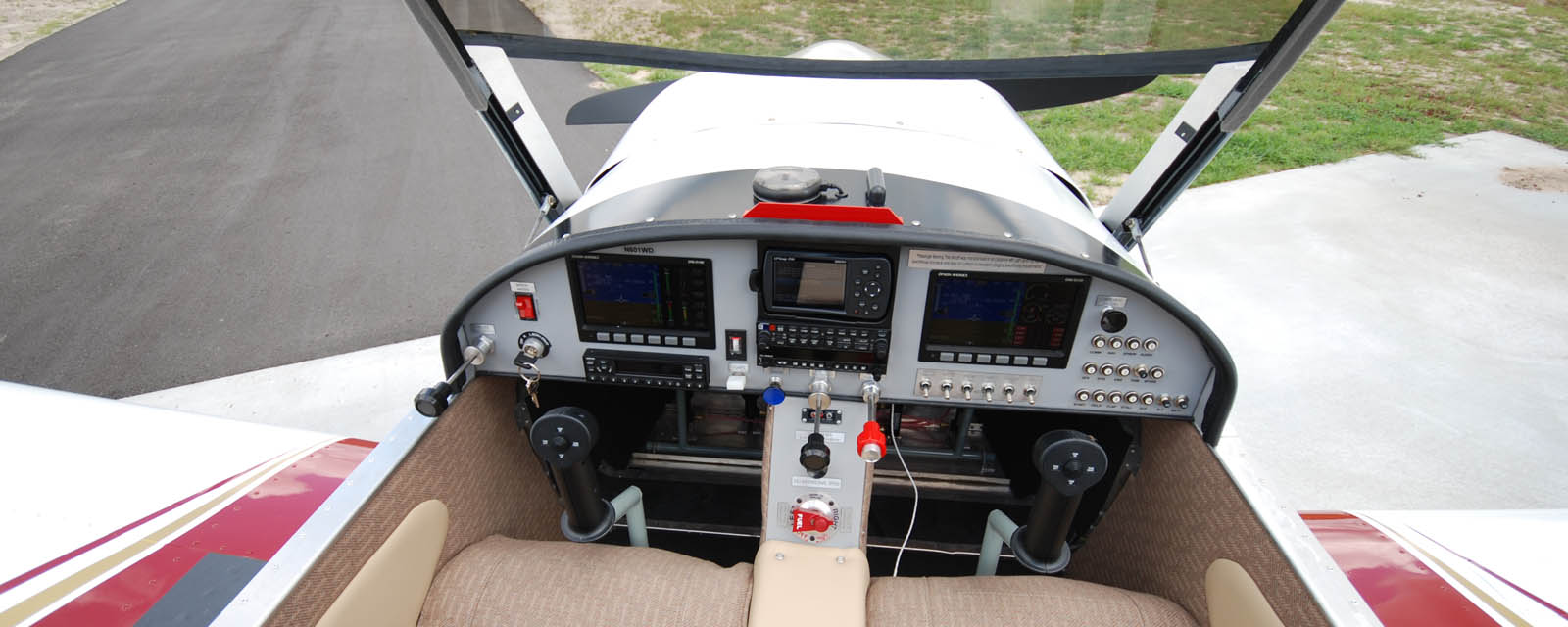
The CH650 Kit
Drawings & Manuals
The detailed Drawings and Manuals guide the builder through the entire kit building process. The drawings and manuals supplied with each kit are not just assembly instructions (as with most kits on the market) but are detailed blueprints of each individual part and component that make up the complete aircraft.
The Drawings (or plans) are 11″ x 17″ blueprints of the entire airframe assembly, and come with an assembly manual and step-by-step Photo Assembly Guides. Supplied with a serial number, you can actually build your own aircraft from “scratch” following the drawings and manuals. If purchased separately, the cost of the drawings and manuals is deductible off the cost of the full kit.

The CH 650 Drawings & Manuals package includes a CD-ROM with high-resolution Photo Assembly Guides for the step-by-step assembly of the kit. The detailed CH 650 Drawings include the drawings for the basic kit options, such as aileron trim tab, installation for the landing and nav/strobe lights, wing lockers, auxiliary fuel tanks, etc. Also included are basic engine mount drawings for the Rotax 912, Jabiru 3300, Continental O-200 and Lycoming O-235 engines. The drawings for the Dual Control Sticks Option and the Tail-Wheel Gear Configuration are available separately for $45.00 each.
Following are selected sample CAD drawings from the drawings.

| Description | Link | Description | Link | |
| Fuselage Sides | 6-B-3 | Canopy Hinge | 6-C-1 | |
| Rudder Pedals | 6-B-9 | Nosewheel Strut | 6-G-1 | |
| Fuselage Bulkheads | 6-B-12 | Wing Spar Attach | 6-W-4 | |
| Cabin Details | 6-B-18 | Wing Aileron Control | 6-W-10 | |
| Control Cables | 6-B-23 | Wing Fuel Tanks | 6-W-13 | |
| Rudder 1 | 6-T-04 | Rudder 2 | 6-T-05 |
Additional Resources
Zenith Aircraft Builder Pages – (Password required)


